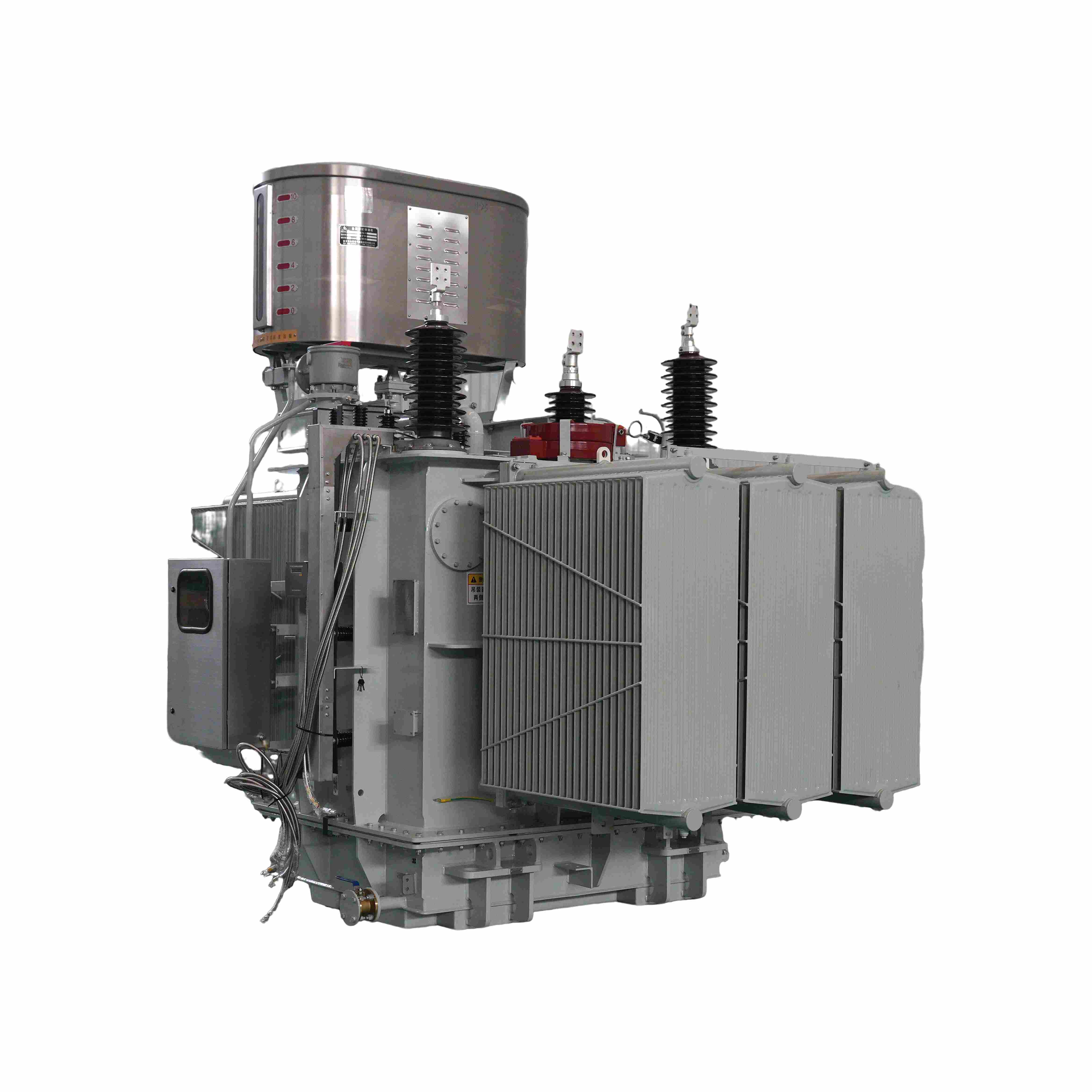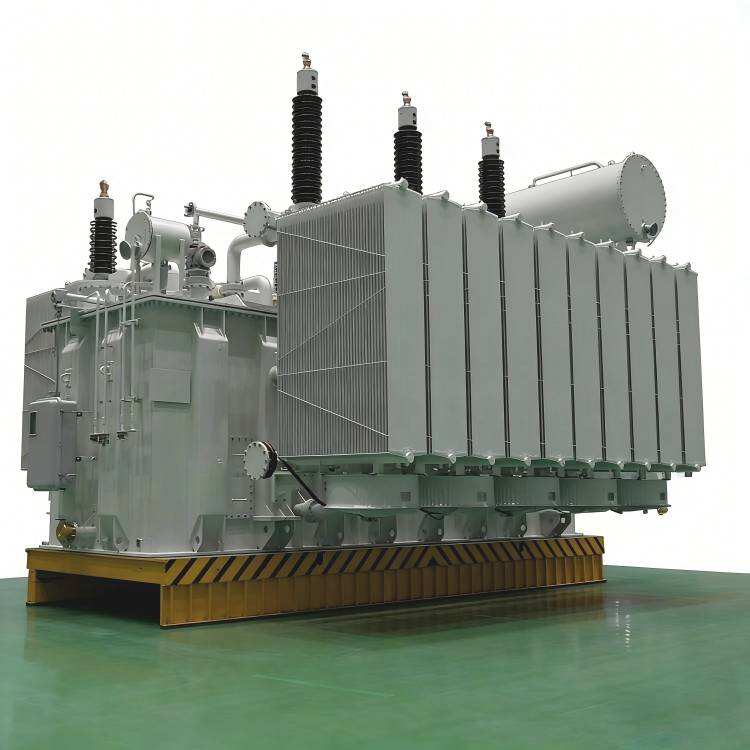
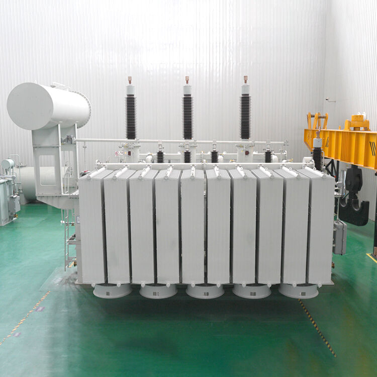
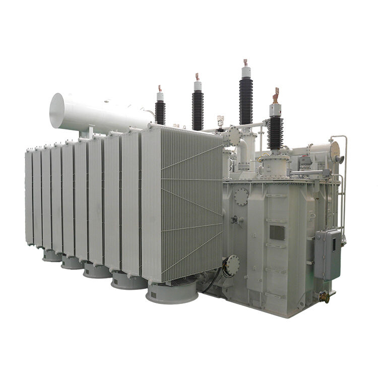
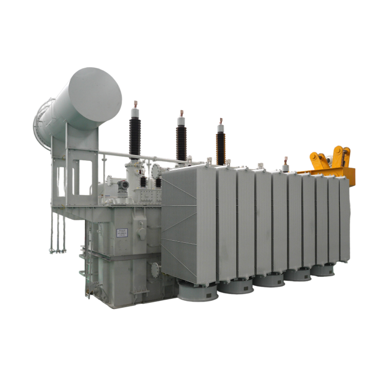
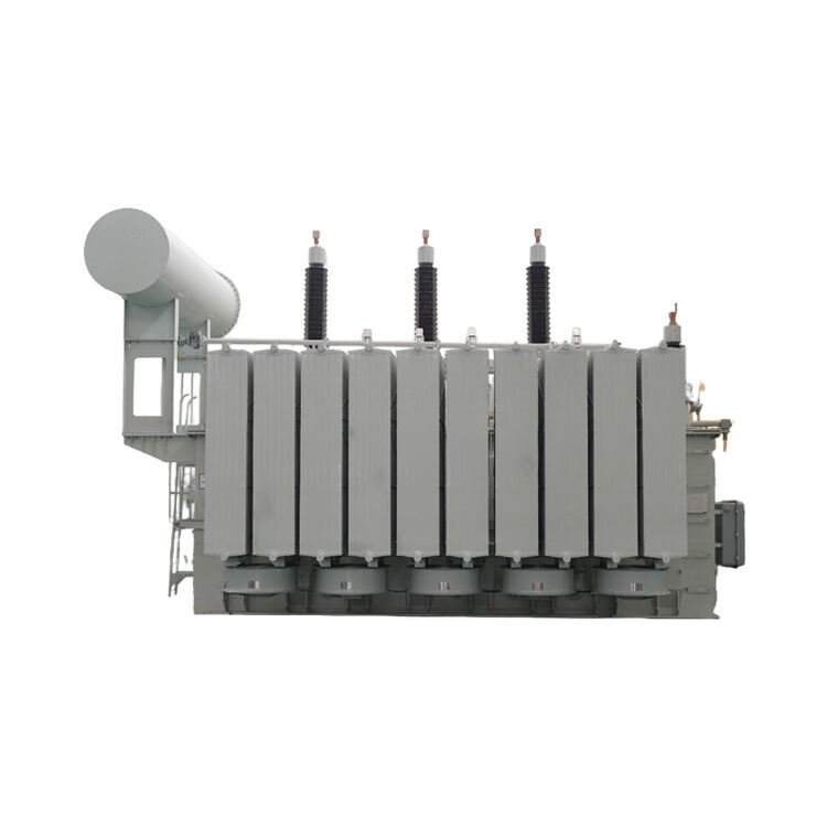
Changzhou Pacific Electric Power Equipment Group’s 400kV power transformers feature low loss, low noise, high efficiency and strong reliability. Adopting advanced design and premium materials, they deliver excellent insulation, low partial discharge and high short‑circuit withstand strength. With stable performance, long service life and compact structure, our transformers are widely used in power grids, industrial and infrastructure projects. They ensure safe and stable operation under various working conditions, providing reliable power solutions for customers worldwide.
Introduction to 400kV Power Transformers
Our company's 400kV power transformers are suitable for 400kV ultra-high voltage power transmission networks. The product fully demonstrates the company's design and manufacturing capabilities in high-voltage and large-capacity transformers, focusing on insulation reliability, low partial discharge levels, and strong short-circuit withstand capacity. The design and manufacturing processes of the core and coils have been optimized for high field strength. All insulating components have undergone pre-stabilization treatment. The body is assembled as a whole and uses a high-strength compression system. The oil tank is of a full vacuum structure, with extremely strict sealing and oil injection processes, effectively preventing insulation from getting damp and the formation of bubbles. The entire production is carried out in a highly clean environment, with strict process quality control, meeting the performance requirements of high-end transformers for the power grid.
Product Parameters
| Rated Capacity (kVA) | Voltage Combination | Connection Group Symbol | No-load Loss (kW) | Load Loss (kW) (75℃) | No-load Current (%) | Short-circuit Impedance (%) | ||
| High Voltage (kV) | High Voltage (kV)% |
Low Voltage kV |
22 | |||||
| 3150 |
35~ 38.5 |
±2x2.5% 土5% |
3.15 6.3 10.5 |
Yd11 |
1.7 | 20.7 | 0.45 | 7.0 |
| 4000 | 2.0 | 24.6 | 0.45 | |||||
| 5000 | 2.4 | 28.2 | 0.35 | |||||
| 6300 | 2.9 | 31.5 | 0.35 | 8.0 | ||||
| 8000 | ±2x2.5% |
3.15 3.3 6.3 6.6 10.5 |
YNd11 | 4.0 | 34.6 | 0.30 | ||
| 10000 | 4.8 | 40.8 | 0.30 | |||||
| 12500 | 5.5 | 48.4 | 0.30 | |||||
| 16000 | 6.7 | 59.2 | 0.25 | |||||
| 20000 | 7.9 | 71.6 | 0.25 | |||||
| 25000 | 9.4 | 84.6 | 0.28 | 10.0 | ||||
| 31500 | 11.1 | 100.8 | 0.28 | |||||
|
Rated Capacity kV-A |
Voltage Combination | Connection Group Symbol | No-load Loss (kW) | Load Loss (kW) | No-load Current (%) | Short-circuit Impedance (%) | |
| High Voltage and Tap Range (kV) | Low Voltage | 22 | |||||
| 6300 |
110±2x2.5% 115±2x2.5% 121±2x2.5% |
6.3 6.6 10.5 |
YNd11 | 4.1 | 32.0 | 0.62 | 10.5 |
| 8000 | 4.9 | 38.0 | 0.62 | ||||
| 10000 | 5.8 | 45.0 | 0.58 | ||||
| 12500 | 6.8 | 53.0 | 0.58 | ||||
| 16000 | 8.3 | 65.7 | 0.54 | ||||
| 20000 | 9.7 | 79.0 | 0.54 | ||||
| 25000 | 11.4 | 94.0 | 0.50 | ||||
| 31500 | 13.5 | 111 | 0.48 | ||||
| 40000 | 16.2 | 133 | 0.45 | ||||
| 50000 | 19.4 | 158 | 0.42 | ||||
| 63000 | 22.9 | 187 | 0.38 | ||||
| 75000 |
13.8 15.75 18 21 |
26.0 | 212 | 0.33 | 12~14 | ||
| 90000 | 29.9 | 245 | 0.30 | ||||
| 120000 | 37.3 | 303 | 0.27 | ||||
| 150000 | 44.1 | 359 | 0.24 | ||||
| 180000 | 49.5 | 411 | 0.20 | ||||
|
Note 1: For step-up transformers, a tapless structure is recommended. Taps can be provided if required by operation. Note 2: When the annual average load factor of the transformer is between 42% and 46%, the maximum operating efficiency can be achieved using the loss values in the table. | |||||||
|
Rated Capacity kV-A |
Voltage Combination | Connection Group Symbol | No-load Loss (kW) | Load Loss (kW) | No-load Current (%) | Short-circuit Impedance (%) | |
| High Voltage and Tap Range (kV) | Low Voltage | 22 | |||||
| 31500 |
220±2×2.5% 242±2×2.5% |
6.3 6.6 10.5 |
YNd11 | 15 | 115 | 0.56 | 12~14 |
| 40000 | 18 | 134 | 0.56 | ||||
| 50000 | 21 | 161 | 0.52 | ||||
| 63000 | 25 | 188 | 0.52 | ||||
| 75000 |
10.5 13.8 |
29 | 213 | 0.48 | |||
| 90000 | 34 | 246 | 0.44 | ||||
| 120000 | 41 | 304 | 0.44 | ||||
| 150000 |
10.5、13.8 11、13.8 15.75 18、20 |
49 | 360 | 0.40 | |||
| 160000 | 51 | 378 | 0.39 | ||||
| 180000 | 56 | 413 | 0.36 | ||||
| 240000 | 70 | 484 | 0.33 | ||||
| 300000 |
15.75 18 20 |
83 | 577 | 0.30 | |||
| 360000 | 95 | 662 | 0.30 | ||||
| 370000 | 97 | 675 | 0.30 | ||||
| 400000 | 103 | 716 | 0.28 | ||||
| 420000 | 106 | 742 | 0.28 | ||||
| Note 1: Transformers with a rated capacity of less than 31500 kVA and those with other voltage combinations can also be provided upon request.Note 2: Transformers with a low voltage of 35 kV and 38.5 kV can also be provided upon request. | |||||||
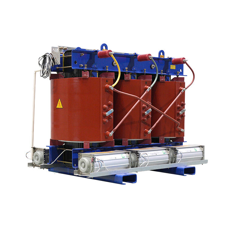
Product Introduction
Transformer Features
Our company manufactures transformers with the following characteristics: low loss, low noise, low partial discharge, no leakage, and strong short-circuit resistance. They do not require core lifting during on-site installation, and the transformer body is maintenance-free for 20 years. Below are the main features of transformers with voltage ratings below 110 kV in terms of structure and process.
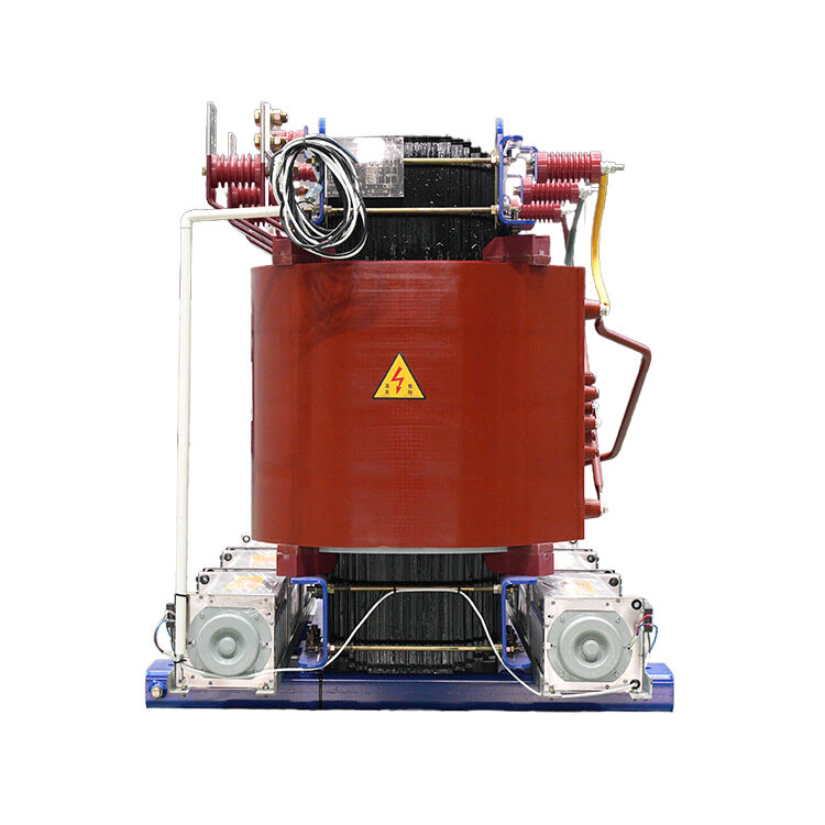
Core Section
1.Core Material and Structure
High-performance grain-oriented silicon steel sheets are selected for the core. The core adopts a fully oblique multi-stage step joint structure, and the non-overlapping yoke process is used, which helps reduce no-load losses and noise.
2.Core Assembly
The core column and yoke are bound using high-strength resin mesh banding materials, mechanically bundled and cured. This ensures good core perpendicularity.
3.Mechanical Strength
The core structure has high mechanical strength. Notably, the frame structure made of large laminated clamp plates effectively clamps the core together, ensuring sufficient short-circuit mechanical strength. This design also meets the requirement for no core lifting during transportation and on-site installation.
4.Core Connectors
All core structural components are rounded to avoid sharp edges. In areas with high field strength where lead wires pass through, special insulation sheaths are added to reduce partial discharge.
5.Electrical Reliability
All core component connections are left unpainted to ensure reliable electrical connection and prevent localized electrical potential. Both the clamps and core are grounded separately.
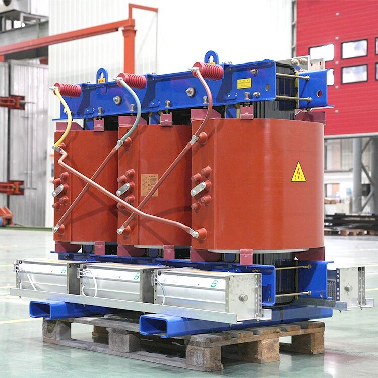
Coil Section
1.Electrical Structure Design
Electrical structural parameters are calculated using analysis software.
2.Voltage Distribution
All coils are analyzed using wave process calculation software for voltage distribution and repeatedly adjusted to ensure a reasonable gradient distribution. The electrical field strength of the transformer body is also verified to ensure optimal main longitudinal insulation parameters and electrical strength.
3.Coil Insulation
All coils are wound on hard insulation tubes that have been pre-dried and impregnated with oil for pre-stabilization. The outer coils are supported with external support strips, and additional auxiliary support strips are added inside the inner coils to improve short-circuit resistance.
4.Short-Circuit Resistance
Based on short-circuit mechanical force calculations, self-adhesive transposed conductors or semi-rigid conductors are used for the inner coils, which have extremely high mechanical strength and meet short-circuit resistance requirements.
5.Enhanced Short-Circuit Strength
All coil terminals and end parts are bound with high-shrink polyester heat-shrink tubes and heat-shrink tapes to increase short-circuit resistance.
6.Coil Structure and Cooling
The inner and outer coil spacers are designed based on calculated values and may differ, ensuring a rational distribution. The coils are equipped with a guided cooling structure for optimal heat dissipation. In addition, heat-pressed insulation molded parts replace traditional cardboard spacer strips at the coil transposition points. The oil gap spacer blocks are rounded and pre-impregnated, improving axial short-circuit resistance.
7.Vacuum Drying and Assembly
After vacuum drying, individual coils are assembled in phase. The main oil gap spacers between the coils are fixed using special positioning plates. After vacuum drying the coils, their heights are checked and adjusted to ensure that coils in the same phase are under consistent load, improving short-circuit strength.
Transformer Body Section
1.Body Structure
The transformer body adopts a single-phase structure. The body press plates are made of laminated insulation board or laminated wood, which have sufficient short-circuit impact resistance.
2.Compression Structure
The compression structure of the body uses laminated insulation board press blocks instead of traditional nails, increasing the cross-sectional area of the compression blocks and reducing the compression force. This structure uses hydraulic devices to set a pre-compression force during assembly after the drying process.
3.Lead Supports
All lead supports are made of high-density laminated wood and form a frame structure. Some lead supports are formed using laminated insulation paperboard, which increases both mechanical and electrical strength. All supports use laminated wood insulation nuts with a special anti-loosening structure.
Oil Tank and Assembly Section
1.Vacuum Oil Tank
All transformers rated for 110 kV and below use a fully vacuum-sealed oil tank with a barrel-shaped structure. The upper and lower sections of the oil tank can be connected either by bolts or welded to meet the requirement for no core lifting and maintenance-free operation. The inside of the oil tank is fully polished and rounded.
2.Oil Conservator
All transformer oil conservators can withstand full vacuum strength and are equipped with airbags and pointer-type oil level indicators. After all transformer accessories are assembled, the conservator can be evacuated to a full vacuum before oil injection, effectively preventing the formation of bubbles inside the insulation components and transformer, reducing partial discharge.
3.Sealing Structure
The sealing surfaces of the transformer, including bushings, adopt a hard connection structure with limit grooves, and high-quality sealing components are used with sealing adhesives to ensure no leakage.
4.Positioning and Reliability
The transformer is equipped with a special upper and lower positioning structure, which ensures reliability, resistance to transportation shocks, and meets the requirement for no core lifting during installation.
5.Secondary Wiring
Secondary wiring is arranged according to the user’s requirements, using stainless steel cable trays or armored cables, and all wiring is connected to terminal boxes to facilitate user installation.
6.Advanced Assembly Process
The transformer body undergoes an equivalent exposure time control from drying to vacuum oil impregnation, ensuring continuous high-vacuum degassing during the assembly of all accessories. This effectively controls moisture absorption in insulation components.
Quality Control
Our company’s entire transformer production process follows an advanced process management system for quality control. Processes such as wire production, insulation material fabrication, coil manufacturing, and body assembly are all carried out in dust-free work zones, with the air cleanliness controlled to 3 μg/cm²·day or below.
Company Profile
Changzhou Pacific Electric Equipment (Group) Co., Ltd. Is a Chinese manufacturer of high and low voltage power transmission and distribution equipment with an international perspective. Since its establishment in 1989 and the groupization development in 1997, the company has a registered capital of 130 million yuan. Its products and services comply with international standards and are targeted at the global market.
The company operates a modern manufacturing base covering an area of 240,000 square meters, with a construction area of 120,000 square meters and fixed assets of 500 million yuan. The annual production capacity exceeds 20,000 sets, and it possesses the supply capability to serve customers worldwide.
Our core advantages are based on international standards and global practices:
Active participants in international industry activities: As a standing member of the China Electrical Equipment Industry Association and a member of multiple international standard alignment working groups, the company closely follows the international technological development trends and promotes the alignment of Chinese standards with international standards.
Product range meeting international requirements: Offer high and low voltage switchgear, transformers, power distribution systems and customized solutions that comply with international standards such as IEC and ANSI, meeting the power system requirements of different countries and regions.
Internationalized R&D and Technology Application: The company is a national-level high-tech enterprise. The R&D team pays attention to the global development of power technology, and the products integrate international advanced design concepts to ensure that the technical performance reaches the international advanced level.
International standard manufacturing and quality system: The company has fully implemented the ISO quality management system, and the manufacturing process complies with international environmental protection and safety regulations. The company's testing center has the internationally recognized testing capabilities, providing quality assurance for products to enter the global market.
Extensive international application experience: The product has successfully entered multiple overseas markets and has been applied in power infrastructure projects in regions such as Asia, Africa, and South America, accumulating rich experience in international project services.
Global Customer Service Network: Adhering to the international business principles of "professionalism, integrity, cooperation, and innovation", we provide customized products and round-the-clock technical support that meet local standards for global customers. We are committed to becoming a reliable partner for our customers in the global power market.
With a profound understanding of international standards and extensive experience in serving the global market, the company's products are providing reliable Chinese solutions for the development of electricity around the world.

Changzhou Pacific Electric Power Equipment (Group) Co., Ltd. provides high/low voltage power transmission equipment, traction transformers (110–330kV), and pad-mounted/package substations for global energy infrastructure. ISO-certified, R&D-driven since 1989. Request a technical consultation today.
Environmental Protection Fourth Road, Environmental Protection Industrial Park, Tongjiang Avenue, XinBei District, Changzhou City, Jiangsu Province
Copyright © 2026 Changzhou Pacific Electric Equipment (Group) Co., Ltd. All rights reserved. Privacy Policy