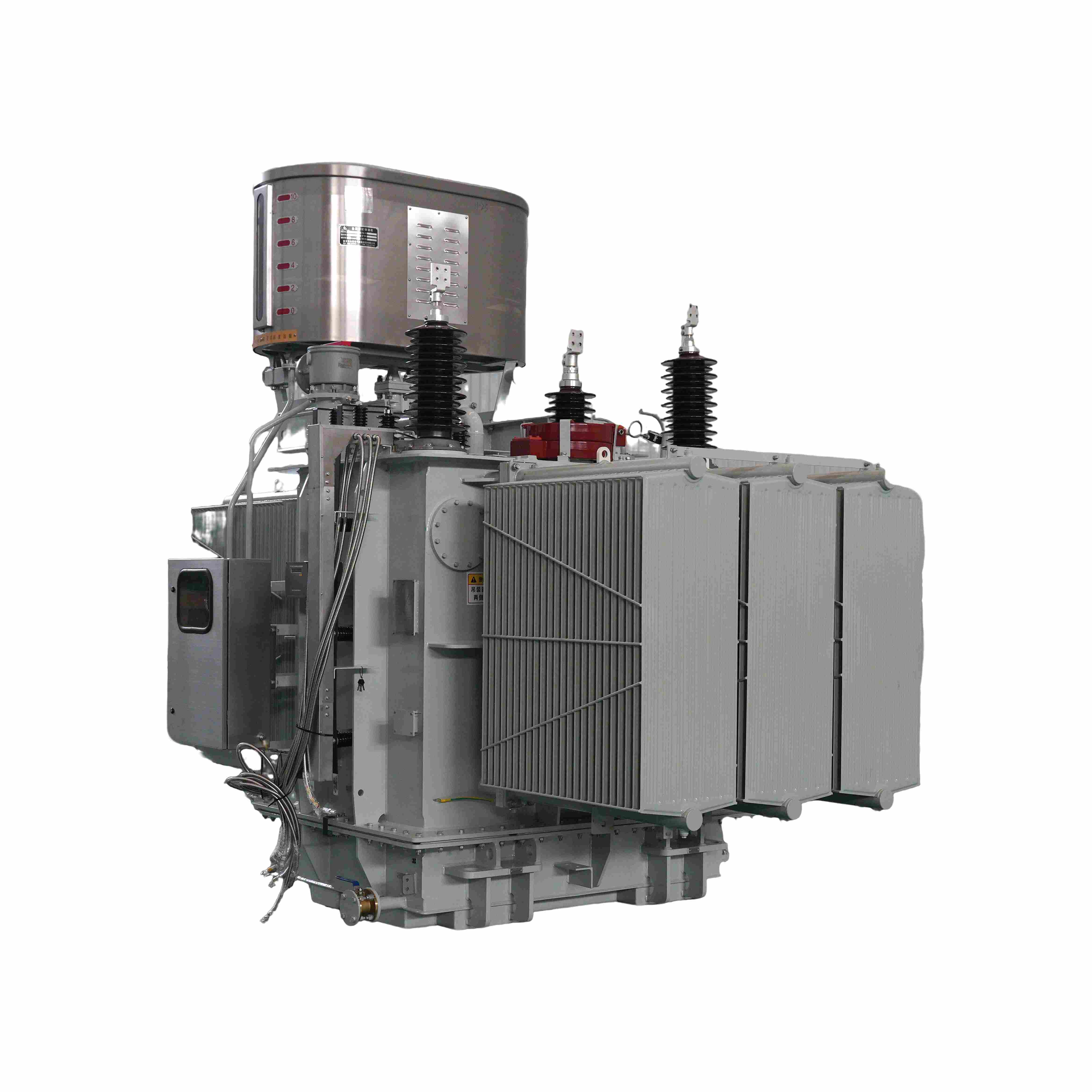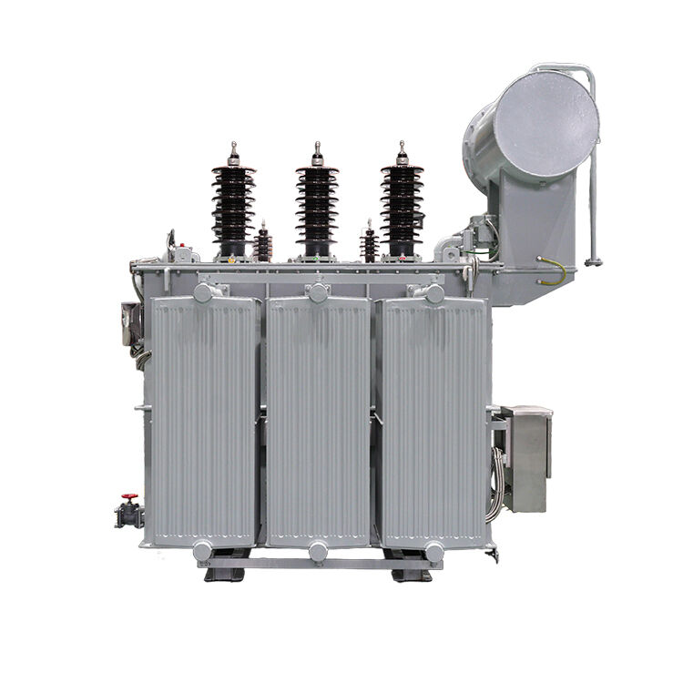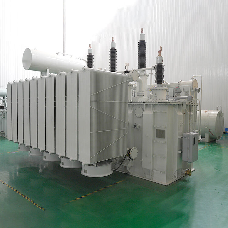
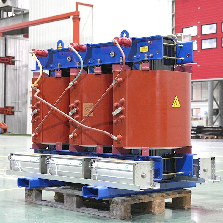
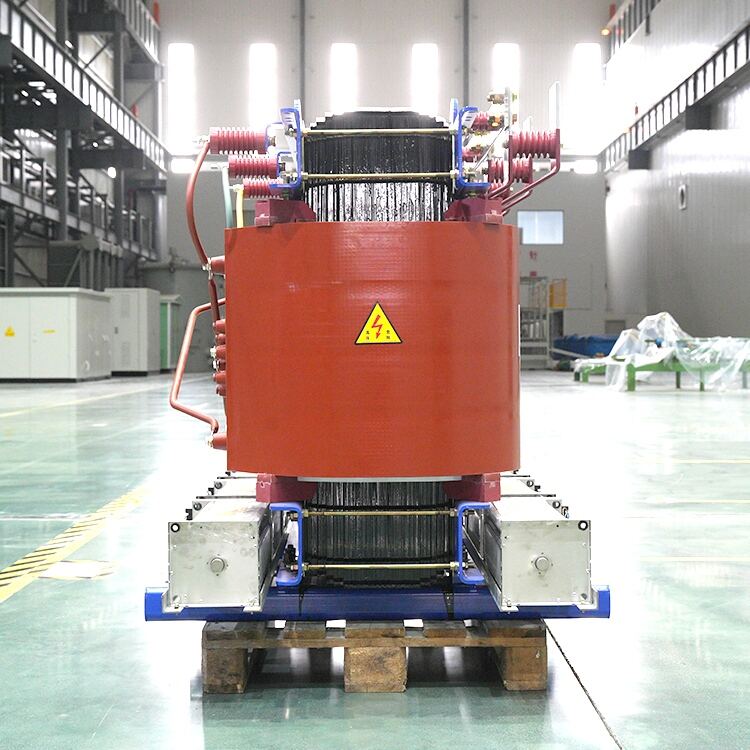
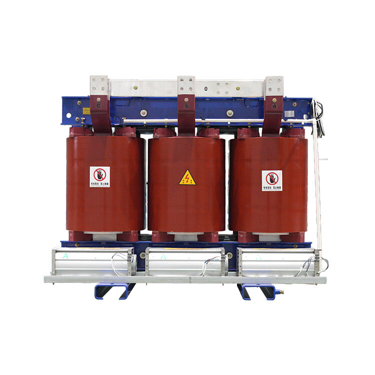
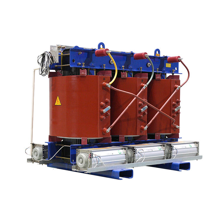
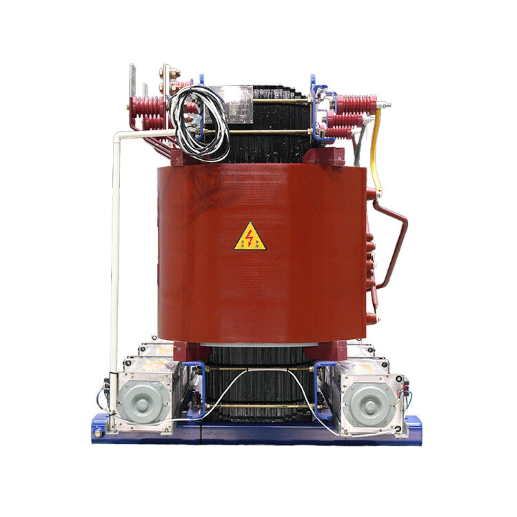
Changzhou Pacific Electric Power Equipment Group’s epoxy resin dry-type transformers feature fire-retardant, flame-resistant, and pollution-free properties, ensuring high safety and environmental protection. With excellent insulation, low loss, low noise, and strong overload capacity, they are highly reliable and maintenance-free. Compact and durable, they adapt well to humid, dusty, and harsh environments. Widely used in urban substations, commercial buildings, hospitals, and industrial facilities, they provide safe, stable, and efficient power solutions for global customers.
Product Parameters
Technical specification of 10kv SCB18 transformer
| Rated capacity(KVA) | Voltage combination(KV) | Connection symbol | No-loadcurrent(%) | Impedance voltage(%) | No-load loss(W) | Load loss(W)(145℃) | ||
| HV(kV) | Tapping | LV(kV) | ||||||
| 100 | 10 |
±5% ±2.5% |
0.4 |
Yyn0 Dyn11 |
0.4 | 4 | 230 | 1520 |
| 125 | 0.36 | 270 | 1780 | |||||
| 160 | 0.32 | 310 | 2050 | |||||
| 200 |
±5% ±2*2.5% |
0.32 | 360 | 2440 | ||||
| 250 | 0.28 | 415 | 2665 | |||||
| 315 | 0.24 | 510 | 3355 | |||||
| 400 | 0.24 | 570 | 3850 | |||||
| 500 | 0.22 | 670 | 4705 | |||||
| 630 | 0.2 | 6 | 750 | 5760 | ||||
| 800 | 0.2 | 875 | 6715 | |||||
| 1000 | 0.18 | 1020 | 7885 | |||||
| 1250 | 0.16 | 1205 | 9335 | |||||
| 1600 | 0.14 | 1415 | 11320 | |||||
| 2000 | 0.14 | 1760 | 14005 | |||||
| 2500 | 0.12 | 2080 | 16605 | |||||
Technical specification of 20kv SCB13 transformer
| Rated capacity(KVA) | Voltage combination(KV) | Connection symbol | No-loadcurrent(%) | Impedance voltage(%) | No-load loss(W) | Load loss(W)(145) | ||
| HV(kV) | Tapping | LV(kV) | ||||||
| 100 | 20 |
±5% ±2.5% |
0.4 |
Yyn0 Dyn11 |
0.6 | 6.0 | 432 | 1920 |
| 160 | 0.6 | 536 | 2380 | |||||
| 200 |
±5% ±2*2.5% |
0.5 | 584 | 2830 | ||||
| 250 | 0.5 | 672 | 3290 | |||||
| 315 | 0.5 | 776 | 3920 | |||||
| 400 | 0.4 | 920 | 4660 | |||||
| 500 | 0.4 | 1080 | 5570 | |||||
| 630 | 0.3 | 1220 | 6590 | |||||
| 800 | 0.3 | 1400 | 7960 | |||||
| 1000 | 0.3 | 1660 | 9360 | |||||
| 1250 | 0.25 | 1900 | 11100 | |||||
| 1600 | 0.25 | 2230 | 13300 | |||||
| 2000 | 0.2 | 2590 | 15800 | |||||
| 2500 | 0.2 | 3100 | 18600 | |||||
Product Introduction
1. Low Loss
In accordance with the spirit of the Energy Conservation Law, the Ministry of Machinery, the National Development and Reform Commission, and the National Science and Technology Commission jointly issued Notification No. 272 [1998] regarding the 18th batch of energy-saving electromechanical products promotion and the 17th batch of eliminating backward electromechanical products. This has set higher requirements for the performance of dry-type transformers. Our company's products, based on the national standard GB/T 10228-1997 Technical Parameters and Requirements for Dry-type Power Transformers, have reduced load loss by 15% and no-load loss by 20% compared to the national standard. This significantly lowers the user's substation costs.
2. Low Noise
Dry-type transformers are increasingly entering spaces where people live and work, essentially becoming part of daily life. This has raised the requirements for noise levels of dry-type transformers. Based on years of production experience, meeting the national noise standards for dry-type transformers is far from sufficient and is not acceptable to users. Therefore, we have made improvements in design, technology, and materials.
First, in the design, we have reduced the magnetic flux density. Based on practical verification, the size of the magnetic flux density in the core directly affects the noise level. Generally, every increase of 1000 Gauss raises the noise by 3 decibels. Thus, the magnetic flux density should not be chosen too high. Based on the characteristics of the hysteresis-saturation curve of silicon steel sheets, the magnetic flux density of the selected core is generally between 1.35T and 1.5T.
In terms of core stacking, we use a five-step staggered stacking method. This method improves the magnetic flux distribution at the core corners compared to the commonly used interleaved stacking method. To make a comparison, the interleaved stacking method arranges the core sheets offset from each other at a certain distance. This forms two parallel gaps in the interleaved area. In these areas with an air gap, the magnetic cross-sectional area is reduced by 50%, and a large portion of the magnetic lines of force cannot smoothly pass through the air gap to reach the adjacent yoke. This leads to increased losses in this region. By using the stepwise five-stage staggered stacking method, each stage is offset by an equal distance. In a certain cross-section of the interleaved area, about 10% of the area is occupied by the air gap, and the magnetic lines of force bypass the air gap and enter the adjacent stack directly. This ensures smooth magnetic flow and reduces no-load loss. As a result, the step-staggered stacking method reduces no-load loss by 6% and noise by 3-5 dB.
In terms of craftsmanship, we have implemented strict measures for binding and clamping the core, and the production is strictly controlled according to technology, which significantly helps in reducing noise.
For materials, we select high-performance materials, such as the Japanese Nippon Steel 30ZH130, 30ZH120, and Wuhan Steel's 30Q130, 30Q120 grain-oriented silicon steel sheets, which also help in reducing transformer noise.
Through these measures, the overall noise level of our transformers is reduced by 8-12 dB compared to the national standard.
3. Low Partial Discharge
The coils of the products we manufacture have changed from the previous four-section design with DMD as inter-layer insulation to a six-section or eight-section design with D711 as inter-layer insulation. This improves the voltage distribution of the coils and prevents incomplete resin penetration when casting with DMD as inter-layer insulation. As a result, the coils can be fully impregnated under vacuum, greatly reducing the factors that lead to partial discharge.
For high-voltage coils, we use materials such as fiberglass tape, non-woven fabric, and chopped mats. These materials not only increase the insulation strength after resin impregnation, forming a fiberglass-reinforced structure, but also fully impregnate with epoxy resin. As a result, there are no voids at the ends, layers, or terminals of the high-voltage coils, eliminating factors that could lead to partial discharge.
Our coil conductors are made from high-quality oxygen-free copper rods. By strictly controlling the quality of the conductors, the wires are free from burrs or sharp edges. The electric field distribution on the conductor surface is uniform, and the distortion factor is minimal, resulting in a small amount of partial discharge.
By carefully controlling the factors that contribute to partial discharge, the partial discharge level of our transformers is controlled to around 5 pC. As is well-known, the level of partial discharge in a dry-type transformer is closely related to the transformer’s lifespan. For this reason, we are committed to producing transformers with no partial discharge.
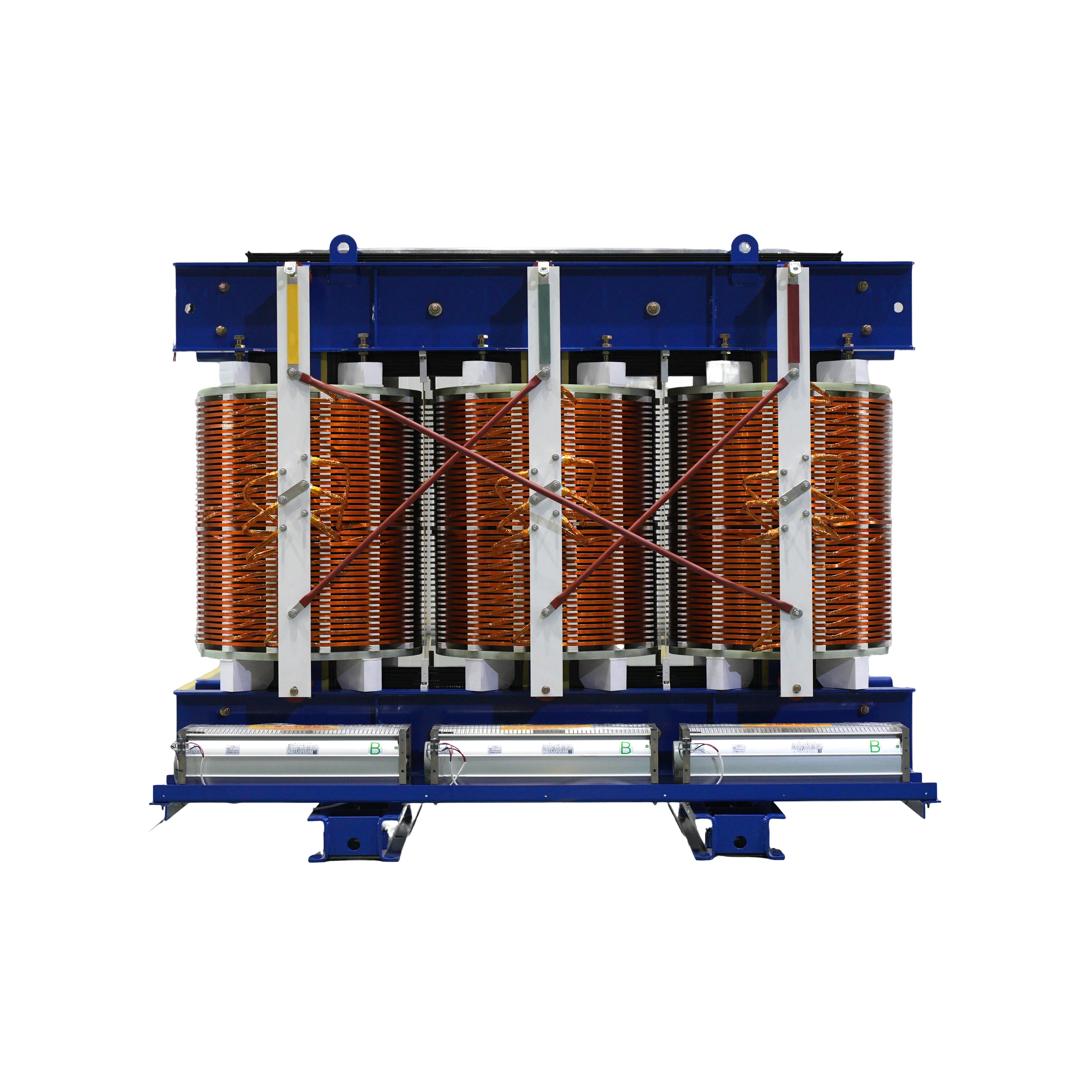
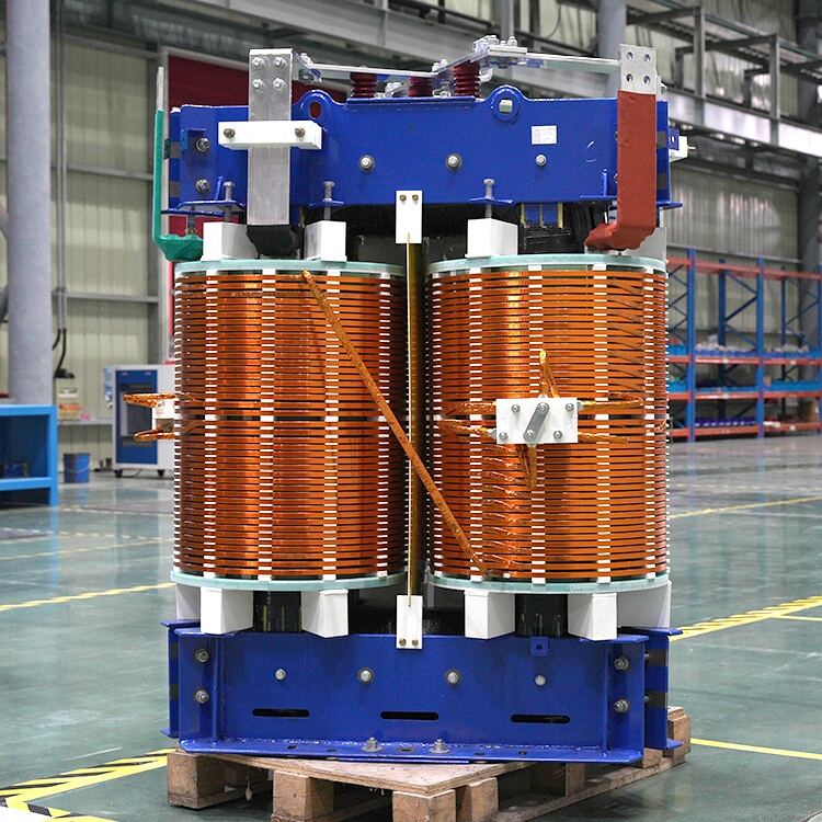
Due to the core adopting a laminated structure, the high-voltage coil is wound, and the low-voltage coil is made from copper foil. This makes the transformer more compact. The laminated structure reduces the transformer’s volume, and the low-voltage copper busbar avoids the need for soldering the copper busbars in a winding style.

Changzhou Pacific Electric Power Equipment (Group) Co., Ltd. provides high/low voltage power transmission equipment, traction transformers (110–330kV), and pad-mounted/package substations for global energy infrastructure. ISO-certified, R&D-driven since 1989. Request a technical consultation today.
Environmental Protection Fourth Road, Environmental Protection Industrial Park, Tongjiang Avenue, XinBei District, Changzhou City, Jiangsu Province
Copyright © 2026 Changzhou Pacific Electric Equipment (Group) Co., Ltd. All rights reserved. Privacy Policy